
- Your cart is empty Browse Shop
What Is a Slewing Bearing?
Also known as slewing rings or turntable bearings, slewing bearings are large-diameter rotary bearings specially engineered to withstand axial loads, radial loads and tilting overturning moments concurrently.
Unlike conventional bearings that only bear unidirectional forces, slewing bearings accommodate three categories of loads simultaneously, rendering them an indispensable core part for heavy-duty rotary machinery.
Slewing bearings feature standard diameters ranging from 200 mm to over 6,000 mm, with custom bespoke units exceeding 8 meters for ultra-specialized working conditions.
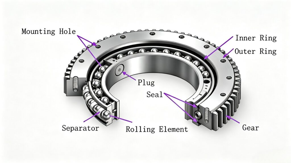
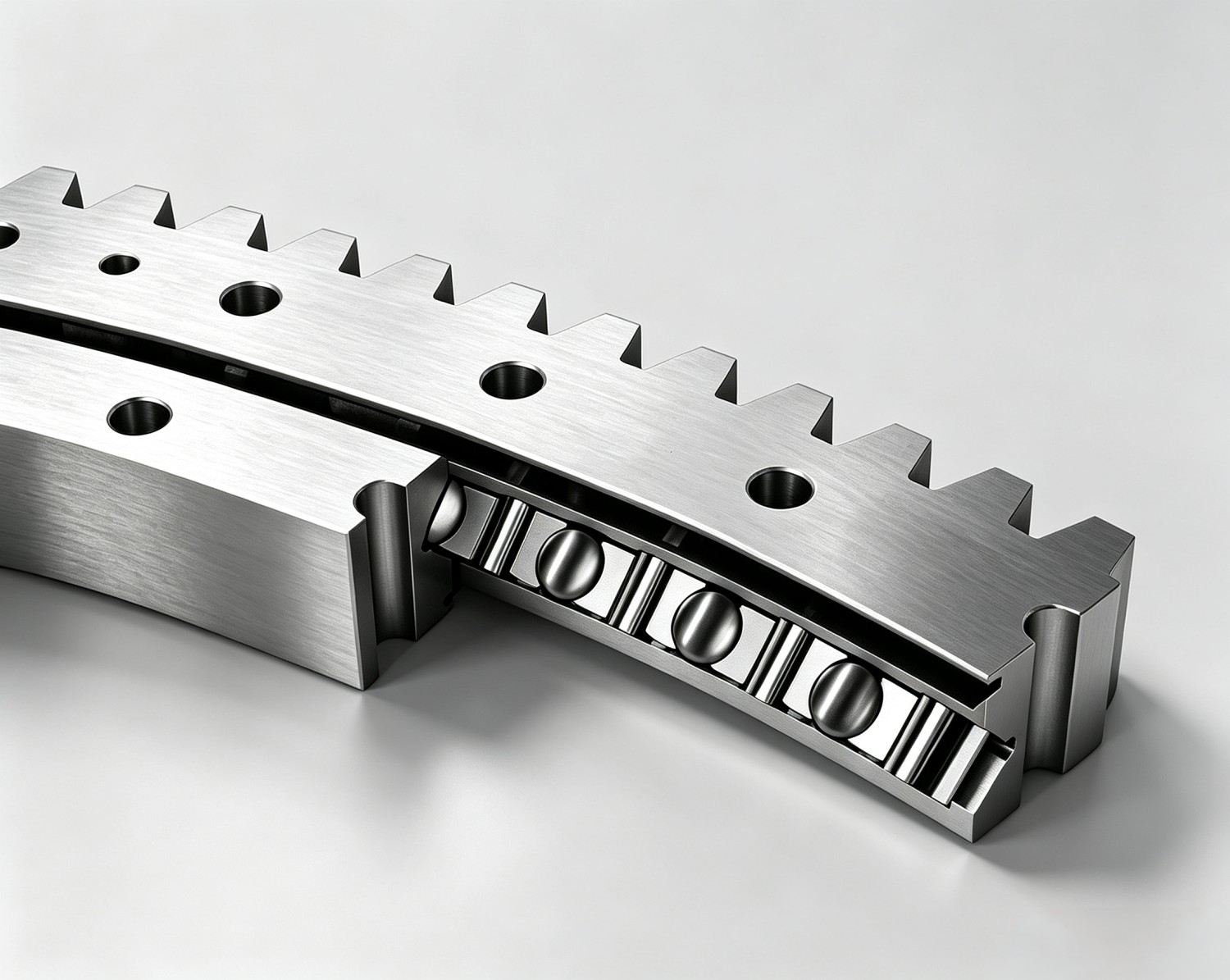
A typical slewing bearing comprises two concentric races (inner ring and outer ring) with rolling elements sandwiched in between. Most models integrate machined gear teeth on either race to deliver powered rotational motion.
This all-in-one compact assembly consolidates the functions of separate bearings, gear rings and support frames, eliminating the need for multiple discrete components.
Figure 1: Structural Diagram of a Slewing Bearing – Inner Ring, Outer Ring, Rolling Elements & Mounting Holes
Quick Reference Specifications
Typical Diameter Range200 mm – 6,000+ mm
Simultaneous Load CapacityAxial load, radial load, overturning moment
Rotational PerformanceFull 360° continuous rotation
Global Annual OutputOver 9 million sets, extensively deployed across all industrial machinery segments
Structure & Core Components
A thorough grasp of each component helps engineers evaluate product specifications, diagnose wear faults and select optimal models for specific working scenarios. Below is a detailed breakdown of each part and its functional role:
1. Inner & Outer Races:
The inner and outer races form the bearing’s primary load-bearing framework. The inner race connects to rotating equipment, while the outer race fastens to fixed base frames. Both are generally forged from medium-carbon alloy steel (predominantly 42CrMo4) to achieve an optimal strength-to-weight ratio for heavy-load applications. Raceways – precision machined grooves on each race – undergo induction surface hardening to a hardness of HRC 55–62, effectively resisting fatigue damage from rolling contact.
2. Rolling Elements (Steel Balls / Cylindrical Rollers):
Sandwiched between raceways, rolling elements transmit loads and enable smooth rotation.
• Steel balls form point contact with raceways, delivering ultra-low friction and superior adaptability to multi-directional composite loads.
• Cylindrical rollers form line contact with raceways, boasting higher single-unit load capacity and outstanding performance under heavy unidirectional forces.
Choosing between ball and roller configurations constitutes one of the most critical decisions in slewing bearing specification.
3. Spacers & Retainers:
Spacers or integrated retainers maintain consistent gaps between rolling elements and prevent direct contact between adjacent balls or rollers. Uniform spacing is vital, as uneven distribution triggers localized stress concentration and accelerates premature wear. Instead of full integral retainers, most large-diameter slewing bearings adopt discrete nylon or steel spacers. This design accommodates more rolling elements along the circumference and significantly elevates overall load-bearing capacity.
4. Sealing Assemblies:
Lip-type seals fitted on both sides of the bearing block external contaminants and retain internal lubricants. Seals for offshore wind turbines and marine cranes must withstand persistent seawater corrosion, while those deployed in mining machinery are engineered to repel abrasive fine dust particles. Seal resistance inevitably generates minor frictional losses – a calculated design tradeoff that safeguards raceway integrity at the expense of slightly higher rotational torque.
5. Mounting Holes:
Bolt layouts and hole quantities are precisely calibrated to distribute clamping force evenly across the bearing races. Insufficient bolt torque causes race deformation under operational loads, while over-tightening distorts the precision-machined raceways. Most manufacturers specify torque standards aligned with ISO 898-1 or equivalent industrial norms, and cross-pattern sequential bolting is recommended to ensure uniform preload across mounting flanges.
6. Optional Integrated Gear Teeth:
Many slewing bearings come with gear teeth directly machined onto the outer race (external gear) or inner race (internal gear). These teeth mesh with motor-driven pinions to deliver controlled powered rotation without standalone gearbox assemblies. External gears are widely adopted for construction machinery, whereas internal gears suit compact equipment where drive units fit within the bearing’s inner diameter.
Operating Principles of Slewing Bearings
Slewing bearings operate based on three core mechanical mechanisms: rolling-element-driven rotary motion, multi-axis synchronous load distribution, and torque transmission via integrated gear structures (for geared variants).
Rotary Motion
When one race rotates relative to the other, rolling elements roll along the raceways rather than sliding – this marks the fundamental distinction between rolling bearings and plain bushings.
Rolling contact reduces the friction coefficient to approximately 0.006, compared with 0.1–0.3 for sliding contact. This enables a medium-power electric motor to drive multi-ton crane superstructures effortlessly.
Constrained by the geometric profile of raceways, rolling elements keep the inner race perfectly concentric with the outer race throughout full 360° rotation.
Such exceptional concentricity delivers high positional accuracy, an indispensable attribute for precision equipment including CT scanner gantries and radar antenna pedestals, where geometric precision directly determines operational performance and output quality.
Synchronous Load Distribution
Slewing bearings simultaneously withstand three distinct types of loads:
- Axial (Thrust) Load: Forces acting parallel to the bearing’s rotational axis, primarily the dead weight of all upper assemblies plus vertical dynamic impact forces. For tower cranes, this encompasses the boom, counterweight and lifting payload transmitted downward through the slewing bearing.
- Radial Load: Horizontal forces perpendicular to the rotational axis, such as wind pressure on crane booms or lateral reaction forces generated during excavator digging operations. Radial loads disperse evenly across the contact zones of circumferentially arranged rolling elements.
- Overturning (Tilting) Moment: A rotational torque generated when loads act at a distance from the bearing’s central axis, creating a tilting force that attempts to offset the two races. For instance, a crane lifting a 10-ton payload at a 20-meter radius produces an overturning moment of 200 ton-meters. This is often the dominant load case for bearing sizing, explaining why bearing diameter carries equal importance to rated load capacity.
These three loads interact simultaneously, and their resultant force disperses across all rolling elements in contact with loaded raceways. A bearing’s official rated load values – separately defined for axial, radial and moment loads – outline its safe operating envelope over the full design service life.
Gear Transmission Mechanism
Geared slewing bearings integrate precision-cut gear teeth onto one race to form an integrated drive interface. An electric motor drives a pinion that meshes with the ring gear to generate controllable rotary motion. The gear ratio between pinion and ring gear delivers torque amplification and speed reduction. Construction cranes commonly adopt reduction ratios of 50:1 or higher, generating the high output torque required to rotate loaded booms.
Classifications of Slewing Bearings
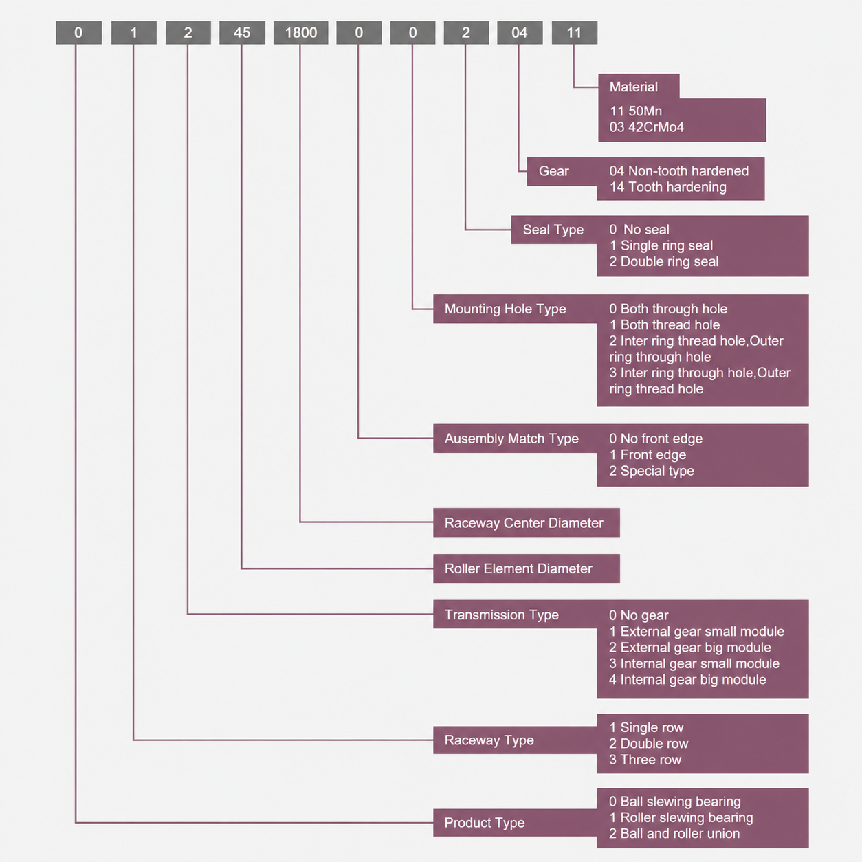
Each slewing bearing variant is optimized for unique load characteristics. Selecting an incompatible model will compromise equipment performance and trigger premature component failure. The key structural differences and application boundaries are outlined below:
| Bearing Type | Load Capacity | Rigidity | Ideal Application Scenarios |
|---|---|---|---|
| Four-Point Contact Ball | Medium | Medium | General multi-directional composite loads |
| Double-Row Eight-Point Ball | Medium-High | High | Complex, fluctuating heavy composite loads |
| Cross Roller | High | Exceptionally High | Precision machinery with compact spatial constraints |
| Three-Row Cross Roller | Ultra-High | Exceptionally High | Super-heavy machinery with separated load-bearing requirements |
| Combined Ball & Roller | High | High | Working conditions with dynamically shifting mixed loads |
Four-Point Contact Ball Slewing Bearings
Each steel ball forms four contact points with raceways: two on the inner race and two on the outer race, achieved via Gothic arch (double V-shaped) raceway profiling.
The four-point contact geometry allows a single row of balls to bear bidirectional axial loads, radial loads and overturning moments at once.
Thanks to its versatile load adaptability, the four-point contact design is the most widely deployed slewing bearing solution. It serves mobile cranes, aerial work platforms and packaging machinery – any equipment requiring a compact all-round rotary bearing.
Trade-off: Under extreme pure overturning moments, contact angles shift and localized stress concentration intensifies. Cross roller or three-row roller bearings are preferred for applications subjected to severe tilting loads.
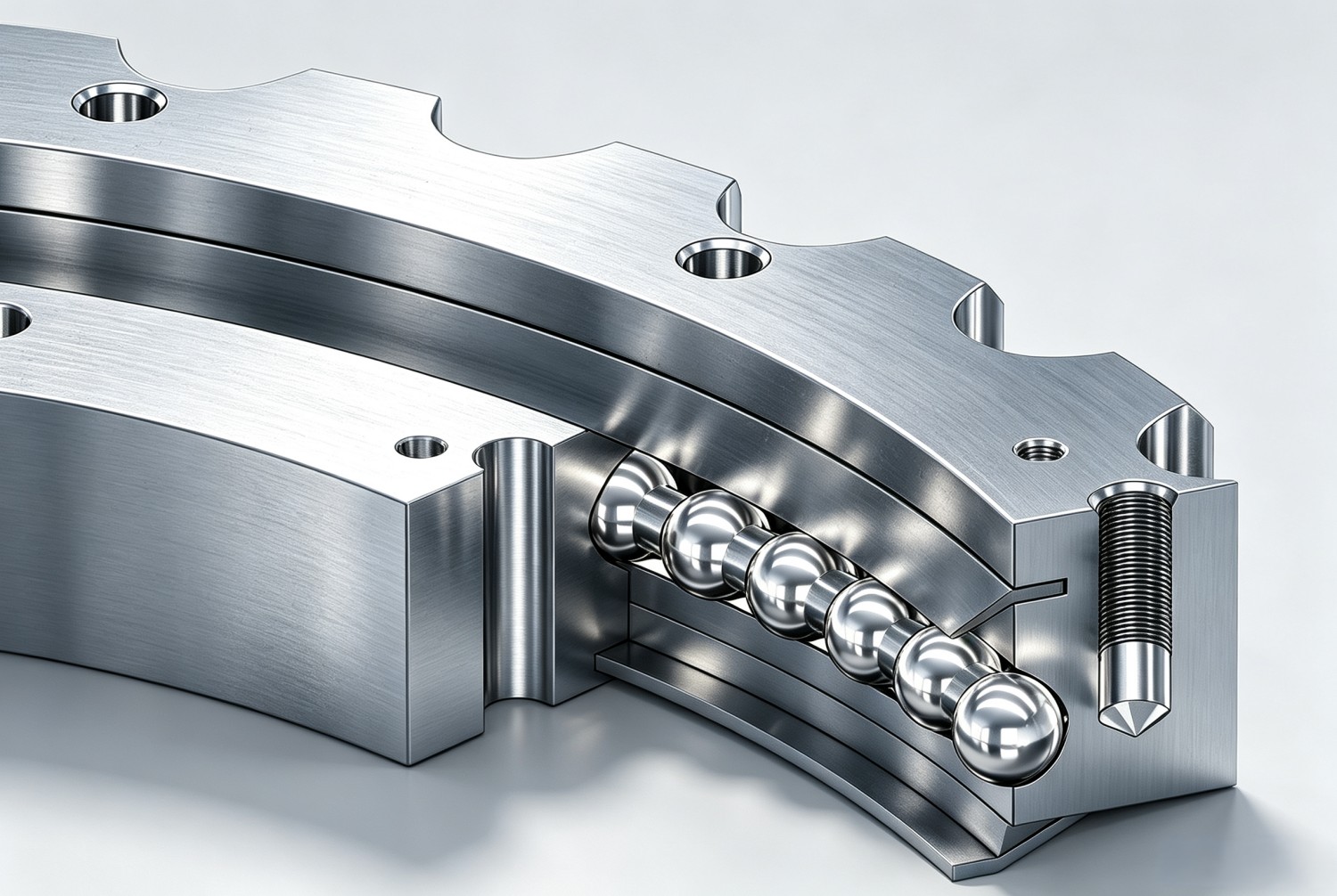
Schematic of Four-Point Contact Ball Slewing Bearing
Double-Row Eight-Point Ball Slewing Bearings
This configuration adopts two parallel rows of balls, each forming four contact points with raceways, creating eight total load-bearing contact zones.
Dual rows double the load distribution capacity compared with single-row four-point bearings. The wider axial span of double rows drastically enhances anti-tilting performance: more contact points spread stress evenly to counteract overturning forces efficiently.
This bearing type suits equipment operating under complex, variable heavy loads, such as tunnel boring machine cutterhead supports and offshore pedestal cranes, where load magnitudes and directions shift frequently during operation.
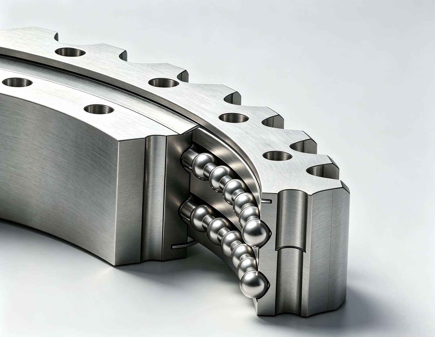
Schematic of Double-Row Eight-Point Ball Slewing Ring
Cross Roller Slewing Bearings
Cylindrical rollers are arranged alternately at 90° intervals around the bearing circumference – one roller aligned horizontally, the next vertically, and so forth.
This staggered layout enables every roller to absorb multi-directional forces without distorting the bearing’s core geometry.
Line contact between rollers and raceways delivers higher single-unit load capacity than the point contact of ball bearings. It also boasts superior rigidity, resisting deflection far better than ball-type alternatives – a critical advantage for precision-critical equipment.
Cross roller slewing bearings are the top choice for robotic joint assemblies, medical imaging equipment and radar pedestals, where high load capacity and strict geometric accuracy must be packed within a limited diameter.
Cross Roller Slewing Ring Schematic – Alternating 90° Roller Arrangement
Three-Row Cross Roller Slewing Bearings
Standard single-row cross roller bearings rely on one alternating roller row to handle all load types, while three-row designs separate load-bearing functions across three dedicated rows: one row for forward axial loads, a second for reverse axial loads, and a third independent row for radial loads, each equipped with dedicated raceways.
Functional separation optimizes each row for its designated load type without performance compromises from multi-directional force demands. The outcome is drastically higher overall load capacity versus single-row bearings of identical diameter, offset by increased axial height and overall weight.
Three-row cross roller bearings cater to the heaviest industrial equipment, including large port cranes handling payloads exceeding 100 tons, steel mill processing machinery and oversized tunnel boring machines. Operators rely on these bearings to sustain continuous heavy-duty operation for over 25,000 hours.
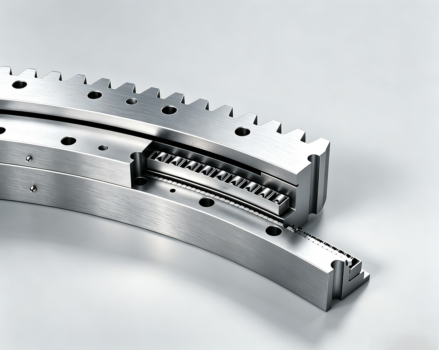
Three-Row Cross Roller Slewing Bearing – Independent Raceways for Axial & Radial Loads
Combined Ball & Roller Slewing Bearings
Combined configurations integrate one row of balls and one row of rollers, with each row optimized for distinct load categories. Ball rows primarily withstand axial loads and overturning moments, while roller rows absorb radial forces.
This functional separation enables independent structural tuning for each row: ball geometry minimizes contact stress under tilting forces, while roller geometry maximizes radial rigidity.
Combined slewing bearings are prevalent on agricultural harvesters, forestry machinery and material handling equipment, where load profiles fluctuate drastically across different operating modes.
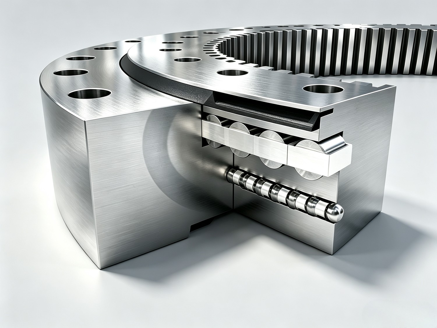
Combined Ball & Roller Slewing Bearing Schematic – Separate Ball and Roller Rows
Cross-Industry Applications
Over 85% of large-diameter rotary assemblies installed on cranes, wind turbines and tunnel boring machines adopt slewing bearings.
The wind energy sector alone accounts for roughly 45% of global slewing bearing demand, with more than 35,000 nacelle-mounted bearing units deployed worldwide by 2023.
Below is a detailed breakdown of industry use cases and corresponding bearing performance criteria:
Construction: Cranes & Excavators
Tower cranes, mobile truck cranes and all-terrain cranes install slewing bearings at the junction between fixed masts/chassis and rotating upper superstructures.
Bearings must support the full dead weight of rotary assemblies plus lifting payloads (surpassing 100 tons for large tower cranes) while maintaining stable 360° rotation under variable wind loads.
Excavators mount slewing bearings between operator cabins and tracked undercarriages, enabling full independent rotation of the entire upper structure. A standard 50-ton excavator generates an overturning moment exceeding 500 kN·m at the slewing bearing during heavy digging cycles.
Wind Energy: Yaw & Pitch Systems
Modern wind turbines deploy slewing bearings at two key functional positions:
- Yaw bearings (typical diameter: 2–4 m): Mounted beneath nacelles to rotate the entire power unit toward incoming wind.
- Pitch bearings (typical diameter: 1–2 m, one per blade): Adjust individual blade angles to regulate power output and shield turbines from damage during extreme wind conditions.
Both bearing variants require a minimum 20-year design service life with minimal routine maintenance. Offshore wind installations face severe corrosion risks, calling for upgraded high-performance sealing systems. Driven by booming offshore wind construction, global demand for double-row ball slewing bearings for marine applications rose 17% year-on-year.
Medical Equipment: CT & MRI Scanners
CT scanner gantries rotate detector arrays and X-ray sources at speeds up to 240 RPM, with premium high-end models exceeding 300 RPM.
Central rotary bearings must support rotating components with sub-millimeter geometric precision; any minor race deflection directly generates image artifacts. Low vibration and ultra-quiet operation are mandatory. Cross roller bearings are widely specified for their exceptional rigidity and compact cross-section. Advanced continuous-rotation systems integrate slip rings within slewing bearing assemblies to transmit electrical signals across rotary interfaces.
Industrial Robotics & Automation
Large industrial robot joints – particularly the base rotary axis and shoulder joints of six-axis manipulators – integrate slewing bearings to merge load support and rotary motion into a single compact component.
Bearings withstand structural robot loads as well as dynamic inertial forces generated by rapid acceleration and deceleration cycles. Miniature slewing bearings are fitted to steering joints of Automated Guided Vehicles (AGVs) and Autonomous Mobile Robots (AMRs) deployed in intelligent logistics warehouses.
These precision applications demand repeat positioning accuracy below 0.01°, requiring bearing tolerance grades of P5 or higher.
Agricultural & Forestry Machinery
Combine harvesters, forestry feller bunchers and tree loaders equip slewing bearings to facilitate rotation of upper working frames atop tracked or wheeled chassis.
Agricultural slewing rings operate under severe contamination conditions: soil, crop residues and chemical fertilizers rapidly degrade standard seals. Limited seasonal maintenance windows and constrained on-site servicing capacity demand outstanding resistance to pollutant ingress and extended lubrication cycles. Combined ball-and-roller designs dominate this segment for their flexible multi-load adaptability.
Solar Tracking Equipment
Single-axis and dual-axis solar trackers rotate photovoltaic panels and concentrated solar collectors to track sunlight throughout the day.
Rotary bearings installed at tracker pivots operate outdoors for project lifespans exceeding 25 years with minimal maintenance, enduring extreme ambient temperatures ranging from desert heat above 60°C to high-altitude cold down to -40°C.
Load requirements remain relatively moderate, consisting mainly of lateral wind forces and panel dead weight, making four-point ball bearings the mainstream choice. Core selection priorities include long-term corrosion resistance and extended lubricant service life.
Port & Marine Equipment
Quayside container cranes, bulk cargo ship loaders and floating cranes rely on large-diameter slewing bearings for all rotary mechanisms. Pedestal cranes fitted on offshore oil and gas platforms deliver stable operation amid vessel rolling and pitching motion, which introduces additional dynamic overturning moments.
Port operating environments combine continuous high-cycle operation with persistent marine salt corrosion, elevating the criticality of premium sealing solutions and anti-corrosion surface treatments.
National Defense: Radar & Weapon Systems
Slewing bearings are deployed on radar antenna pedestals, missile launch turrets and naval gun mounts to deliver precise, controllable rotation under harsh environmental conditions. Over 2,200 new military rotary-integrated systems entered service between 2022 and 2024, fueled by rising global defense expenditure and military equipment modernization initiatives.
These defense applications demand ultra-high angular positioning accuracy (often measured in arcseconds), robust shock resistance and consistent performance across an extreme temperature spectrum.
Slewing Bearing Selection Guidelines
Slewing bearing specification is not a single straightforward choice, but a holistic series of engineering tradeoffs. Improper model selection can slash bearing service life from 20 years to merely two. Below outlines core evaluation criteria; refer to our dedicated Slewing Bearing Selection Manual for a complete step-by-step specification workflow.
Cart (0 items)