
- Your cart is empty Browse Shop
1、Before installation
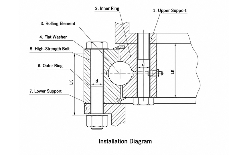
(1) Confirm that the slewing bearing you received matches the requirements specified in the contract and order.
(2) Confirm that the slewing bearing has not been damaged during transportation, especially from radial impacts, to prevent any changes in performance.
(3) Confirm that the sealing strip is not damaged.
(4) Confirm that the slewing bearing model is compatible with the host machine on which it will be installed.
(5) Confirm that the installation of the slewing bearing does not create any associated safety hazards, such as:
— The rotational speed does not exceed the calculated value
— No objects obstruct its rotation
— Safety guards have been installed between the bearing and the pinion gear to eliminate any risk to people or property.
2、Installation Bracket Requirements
(1) The mounting base surface of the slewing bearing and the installation platform must both be thoroughly cleaned. Small debris, welding slag, and corrosion are not permitted.
(2) The mounting bracket must have sufficient rigidity to prevent deformation of the slewing bearing, which could affect its performance.
(3) A cylindrical welded structure is recommended for the mounting bracket. After welding, stress-relief heat treatment and machining should be performed. For slewing bearings with a diameter greater than 3 meters, if machining of the mounting bracket is not feasible, the installation may be carried out using the plastic filling method. If a cylindrical structure is adopted, its wall dimensions should conform to the installation dimensions of the slewing bearing. In particular, the bracket bolt holes must align with the slewing bearing mounting holes (bolt holes or threaded holes) to avoid installation-induced deformation.
(4) The flatness of the mounting bracket’s installation surface, including the angular deviation from horizontal, should be controlled within a specified range. Refer to the table below.
Below is the HTML table code with all headers and content translated into English:
| Raceway Center Diameter DL (mm) | Installation Bracket Surface Flatness Deviation P (mm) within 100 mm Range | ||
|---|---|---|---|
| Single-Row Four-Point Contact | Double-Row Ball | Roller | |
| ~1000 | 0.15 | 0.20 | 0.10 |
| >1000~1500 | 0.19 | 0.25 | 0.12 |
| >1500~2000 | 0.22 | 0.30 | 0.15 |
| >2000~2500 | 0.25 | 0.35 | 0.17 |
| >2500~4000 | 0.30 | 0.40 | 0.20 |
| >4000~6000 | 0.40 | 0.50 | 0.30 |
| >6000~8000 | 0.50 | 0.60 | 0.40 |
(5) Within the 0°–90°–180° sector area, only one peak is permitted to reach this value, and the deviation must rise or fall gradually. Abrupt fluctuations are not allowed to avoid peak loads.
(6) Under maximum working load, the deflection of the mounting surface should be controlled within the range specified in the table below.
Below is the HTML table code with all headers and content translated into English:
| Raceway Center Diameter DL (mm) | ~1000 | >1000 ~ 1500 | >1500 ~ 2000 | >2000 ~ 2500 | >2500 ~ 3000 | >3000 ~ 3500 | >3500 ~ 4000 | >4000 ~ 4500 | >4500 ~ 5000 | >5000 ~ 5500 | >5500 ~ 6000 | >6000 ~ 7000 | >7000 ~ 8000 |
|---|---|---|---|---|---|---|---|---|---|---|---|---|---|
| Maximum Bracket Surface Slope Amax (mm) | 0.6 | 0.8 | 1 | 1.3 | 1.6 | 2 | 2.5 | 3 | 3.6 | 4.2 | 4.8 | 5.8 | 7 |
3、Installation
(1) Place the slewing bearing horizontally onto the mounting bracket and use a feeler gauge to check the contact between the bearing support surface and the mounting base surface. If gaps exist, use plastic filling or local shims to fill them to prevent bearing deformation after the bolts are tightened.
(2) During installation, the quenched soft zone of the slewing bearing (located at the external mark “S” and at the plug hole) should be positioned in the non-load zone or non-frequent load zone.
(3) Mark the three teeth with the largest tooth runout on the gear ring using green paint. The backlash of the drive pinion must be adjusted at these positions.
(4) High-strength bolts must be used for slewing bearing installation bolts. Select the appropriate strength grade based on the bearing load conditions.
(5) Quenched and tempered flat washers must be used for the mounting bolts. The use of spring washers is prohibited.
(6) When the slewing bearing mounting holes are threaded holes, manually insert the bolt into the bolt hole and rotate it to engage at least three threads before using a pneumatic tool to tighten, to avoid damaging the threaded mounting holes.
(7) The mounting bolts must have sufficient preload, which should be 0.7 times the yield limit of the bolt material. A torque wrench must be used during installation. For mounting bolts that have been strictly calculated based on load, specification and quantity, refer to the table below for the actual preload torque or preload force:
Below is the HTML table code with all headers and content translated into English:
— MA = 0.9 Msp (permissible clamping torque)
— FA = 0.9 Fsp (permissible clamping force)
— If the bolt size does not conform to GB5782 or GB5783, the table values must be recalculated separately.
— The total friction coefficient between the bolt head and the clamped surface is μ = 0.14, with the threads lightly coated with light oil.
— The clamping length LK = 5d (bolt diameter) — The nut strength grade shall comply with the provisions of GB3098.2-82 and may be one grade lower than the bolt strength.
(8) Before tightening the mounting bolts, a gear meshing inspection must be carried out to ensure that the backlash at the highest points of the gear ring runout (the three teeth marked with green paint) meets the design precision requirements.
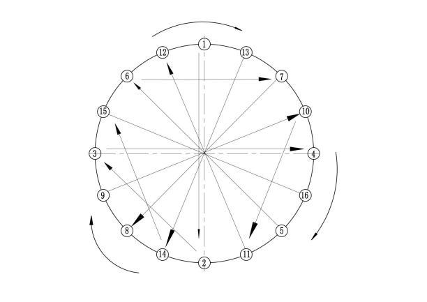
(9) The mounting bolts must be tightened continuously and symmetrically in the 180° direction, and finally make one full circle to ensure that all bolts on the circumference have the same preload.
Tighten the bolts in the sequence shown in the figure below:
| Bolt Specification GB5782-86 GB5783-86 | Mounting Hole Diameter (mm) | Bolt Strength Grade GB3098.1-82 | ||
|---|---|---|---|---|
| 8.8 | 10.9 | 12.9 | ||
| Minimum Yield Strength of Bolt Material σsmin (N/mm²) | ||||
| 640 | 900 | 1080 | ||
| Pre-tightening Torque MA (N·m) | ||||
| M10 | 11 | 44 | 62 | 75 |
| M12 | 13.5 | 77.5 | 110 | 130 |
| M14 | 15.5 | 120 | 170 | 210 |
| M16 | 18 | 190 | 265 | 320 |
| M18 | 20 | 260 | 365 | 435 |
| M20 | 22 | 370 | 520 | 620 |
| M22 | 24 | 500 | 700 | 840 |
| M24 | 26 | 640 | 900 | 1080 |
| M27 | 30 | 950 | 1350 | 1620 |
| M30 | 33 | 1300 | 1800 | 2160 |
| Preload FA (10³ N) | ||||
| M33 | 36 | 293 | 412 | 495 |
| M36 | 39 | 344 | 484 | 581 |
| M39 | 42 | 414 | 581 | 698 |
| M42 | 45 | 473 | 665 | 798 |
| M45 | 48 | 553 | 777 | 932 |
| M48 | 52 | 623 | 876 | 1050 |
| M52 | 56 | 749 | 1054 | 1265 |
| M56 | 62 | 863 | 1214 | 1457 |
| M60 | 66 | 1008 | 1418 | 1621 |
4、After installation
(1) Confirm that the installation does not cause any deformation that affects the slewing bearing.
(2) Confirm that the installation does not create any deformation that could reduce the service life of the slewing bearing.
(3) It is prohibited to connect ground wires, weld on the bearing or other components near the slewing bearing.
(4) After all bolts are tightened, rotate the slewing bearing for more than 3 full revolutions. Check whether there is any interference with other components during rotation, whether the sealing ring is intact, and whether there are any abnormal noises. After rotation, re-measure the backlash values and record these data.
5、Use and Maintenance
(1) Upon delivery, the raceways of the slewing bearing are pre-lubricated with a small amount of No. 2 extreme-pressure lithium-based grease (GB7323-1994). Before commissioning, the user should refill with fresh grease according to the specific working conditions.
(2) Under normal working conditions, ball-type slewing bearings should be lubricated every 100 operating hours, and roller-type slewing bearings every 50 operating hours. In tropical regions, or where there is high humidity, heavy dust, significant temperature variation, or continuous operation, lubrication should be performed weekly. Fresh grease must also be added before and after long-term storage or shutdown. During each lubrication, the raceway must be completely filled with grease until it begins to seep out from the seals. While lubricating, slowly rotate the slewing bearing to ensure even distribution of the grease.
(3) The gear teeth should be cleaned of debris every 10 working days and then coated with grease. The grease can be selected according to the table below:
| Support Structure | Operating Conditions | Lubrication Point | Grease | |||
|---|---|---|---|---|---|---|
| Name | Quality Grade | Standard No. | ||||
| Nylon Spacer Block with Rubber Ring Seal | Low Temperature, Ambient Temperature and Humid Conditions: -20°C to +60°C | Raceway | Extreme-Pressure Lithium-Based Grease | No. 1 / No. 2 | GB7323-1994 | |
| Gear | Graphite-Based Lubricant | ZG-S | SH/T0369-1992 | |||
| Metal Spacer Block Labyrinth Seal | High-Temperature and Humid Conditions | 40°C to 120°C | Raceway | Extreme-Pressure Lithium-Based Grease | No. 1 / No. 2 | GB7323-1994 |
| Gear | MoS₂ Composite Calcium-Based Grease | No. 2 | ||||
| 80°C to 180°C | Raceway | MoS₂ Composite Calcium-Based Grease | No. 2 | |||
| Gear | No. 4 High-Temperature Grease | No. 4 | SH0376-1992 | |||
| Ambient Temperature, Seawater-Corrosion Resistant, up to 50°C | Raceway | No. 2 Composite Aluminum-Based Grease | No. 2 | |||
| Gear | No. 4 Aluminum-Based Grease | No. 4 | SH0378-1992 | |||
Due to the wide range of operating conditions, users should select the most suitable grease based on their specific requirements.
(4) After the slewing bearing has been in operation for 100 hours, the bolt preload should be inspected. Thereafter, it should be checked every 500 operating hours to ensure sufficient preload is maintained. Generally, bolts should be replaced after 7 years of service or 14,000 operating hours.
(5) During operation, pay attention to the running condition of the slewing bearing. If abnormal noise, impact, or a sudden increase in power consumption is observed, stop the machine immediately for inspection and troubleshooting. If necessary, disassemble and inspect the bearing.
(6) Protect the bearing from direct sunlight during use. Do not wash the slewing bearing directly with water to prevent water from entering the raceway. Prevent hard foreign objects from approaching or entering the gear meshing area.
(7) Regularly check the condition of the seals. If the sealing strip is found to be damaged, replace it promptly. If it becomes detached, reposition it immediately.
6、Storage
(1) The slewing bearing is shipped with an oil-sealed packaging. Properly packaged bearings can be stored under suitable conditions for up to 6 months. For idle bearings, the raceway should be lubricated every 12 months (refer to the previous section “Slewing Bearing Lubrication and Maintenance”); idle bearings should be re-packaged with rust-preventive oil-sealing every 6 months.
(2) The oil-sealing packaging procedure is as follows:
– Remove the slewing bearing from the wooden case.
– When unpacking, take care not to scratch the sealing strip; unpack layer by layer from the outermost layer.
– After unpacking, first inject grease into the raceway, degrease the surface, and then proceed with oil-sealing packaging.
– When degreasing, do not use chlorinated solvents. Also take care to prevent solvents from entering the raceway through the sealing strip.
– After degreasing, clean and wipe the external surface, then apply an even coat of rust-preventive grease (F20-1) or industrial petroleum jelly (SY1607-77).
– Then repack according to the original packaging method and place back into the wooden case. It is recommended to line the inside of the wooden case with oil felt for moisture and rain protection. If no wooden case is available after oil-sealing packaging, the bearings may be stacked. Note: When stacking, place at least three evenly spaced wooden blocks of equal height along the circumference between each bearing, and the blocks between layers should be aligned.
(3) When storing the slewing bearing, place it in a dry, flat location and keep it horizontally. Keep it away from water pipes and steam pipes to prevent rusting caused by temperature fluctuations.
7、Packaging and Transportation
(1) Packaging for Truck Transport
Depending on the transport distance, the bearing may be packed in a wooden case, or wrapped with plastic film and woven plastic fabric. Impact and rolling are not permitted. The stacking height must not exceed the truck’s side guardrails. When a wooden case is not used, at least two wooden planks should be placed between the bearing and the truck bed to support it evenly and prevent damage to the bearing end faces.
(2) Packaging for Railway Transport
The bearing must be packed in a wooden case, placed flat, and protected from impact.
(3) Packaging for Maritime Transport
After applying rust-preventive grease to the surface of the slewing bearing, wrap it with wax-coated plastic film or bitumen-coated film in a 50% overlap manner for one to two layers, then wrap with woven plastic fabric strips for one to two layers, and place it into a wooden case. The bearing must be placed flat and protected from impact.
(4) Packaging for Air Transport
– Depending on specific circumstances.
– The wooden case must be sturdy and reliable. In principle, each wooden case should contain one slewing bearing. After placing the bearing into the case, at least three wooden blocks should be evenly distributed along the circumference (either on the inner or outer ring) to secure the bearing and prevent movement.
– Upon delivery, the accompanying documents include the product certificate, installation and operating manual, and packing list (the installation and operating manual may be provided in a single batch as per the user’s request). All documents must be placed in a plastic film bag and wrapped on the inner packaging of the bearing.
– The following markings must be clearly indicated on the wooden case: slewing bearing model and specifications, quantity, consignor, consignee, and labels such as “KEEP FLAT” and “DO NOT DROP / HANDLE WITH CARE”.
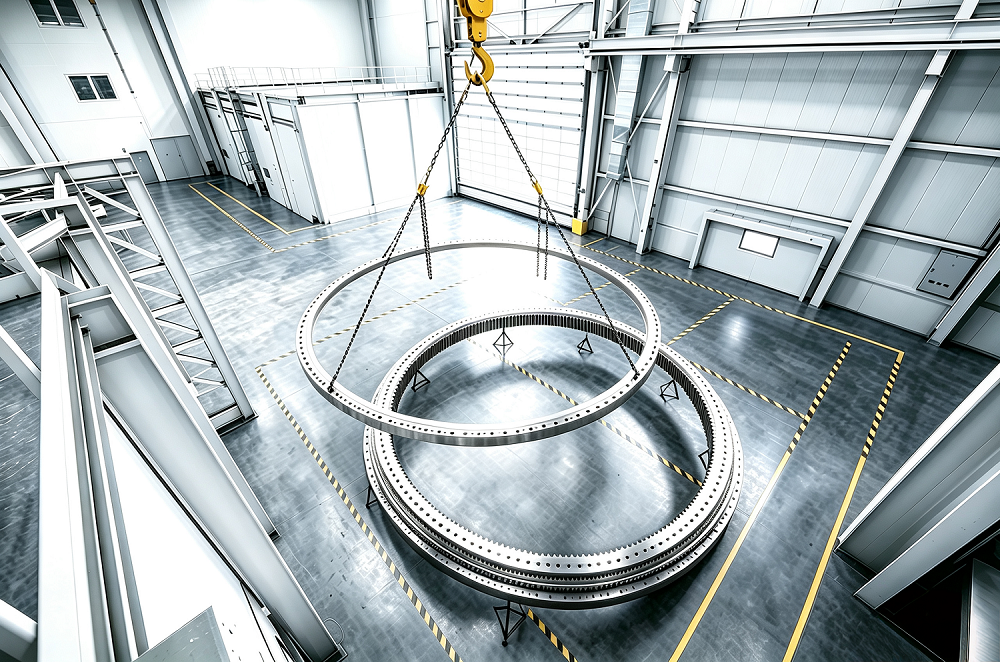
– During lifting, the bearing must be lifted horizontally. Do not lift it vertically by attaching to the circumference of the bearing.
– Avoid impact or shock to the inner/outer rings and gear teeth.
– For bearings larger than 3 meters in diameter, three or more lifting eye bolts should be used to ensure stability and safety (see figure below).
When lifting the slewing bearing, it is recommended to use lifting eye bolts to avoid damaging the bearing and ensure safety.
Cart (0 items)