
- Your cart is empty Browse Shop
Slewing Ring Selection Calculation
Slewing Ring Load Capacity Curves
The product catalog provides a load capacity curve diagram for each slewing ring model. These curve diagrams assist users in making a preliminary selection of the slewing ring.
Three types of curves are presented in the diagram. One type is the static curve (Line 1), which indicates the maximum load that the slewing ring can withstand when it remains stationary. Another type is the slewing ring bolt load curve (Lines 8.8, 10.9, 12.9), which is determined under the conditions that the bolt clamping length is five times the nominal bolt diameter and the preload is 70 percent of the bolt materials yield strength.
Slewing Ring Selection Calculation Method
Selection Calculation Flowchart
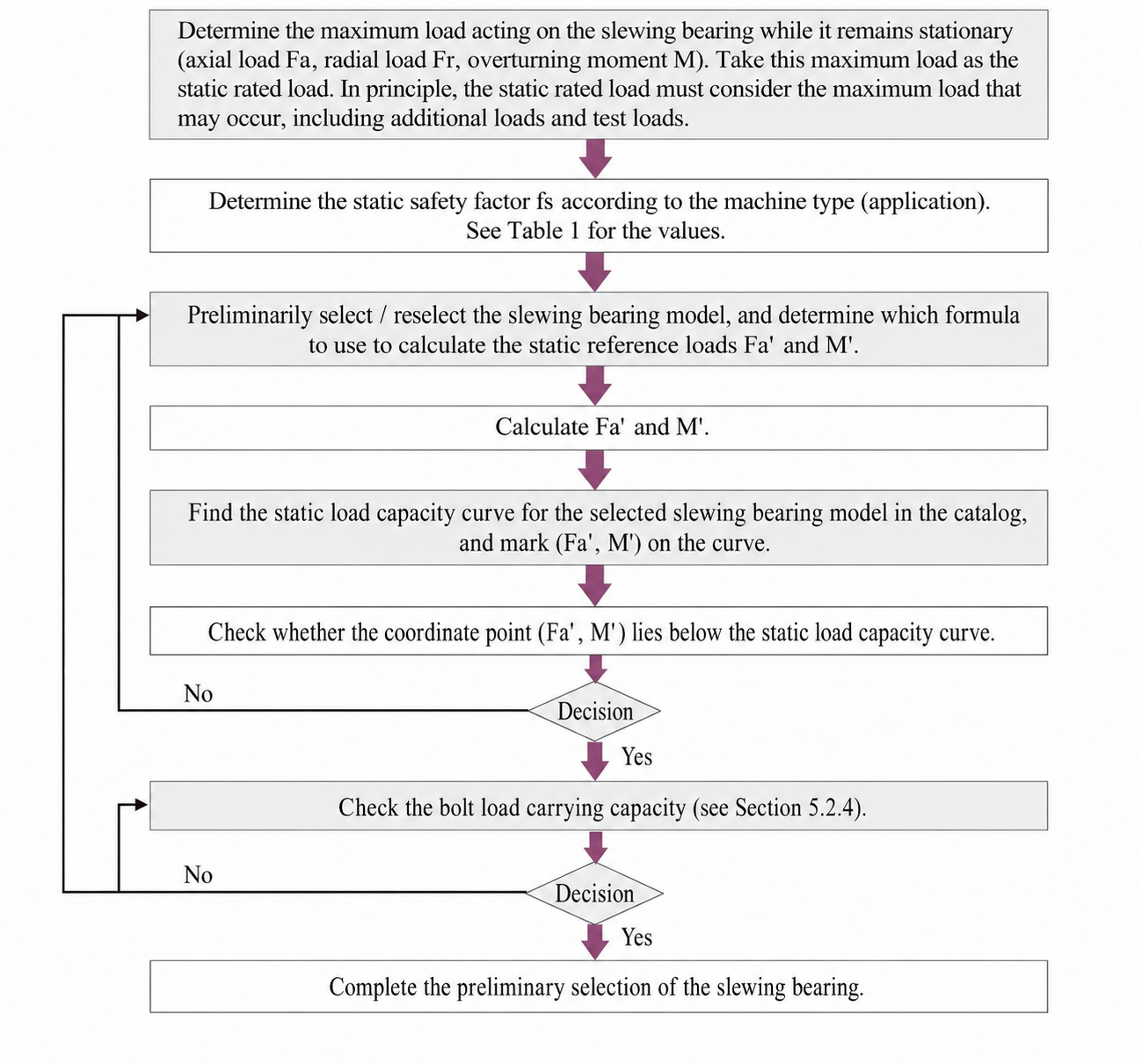
Static Selection
The calculation methods for the static reference loads Fa’ and M’ are as follows:
For the selection calculation of single-row four-point contact ball slewing rings, the calculations are performed separately for contact angles of 45° and 60°.
Method I
Fa’ = (Fa + 5.046 × Fr) × fs
M’ = M × fs
Method II
Fa’ = (1.225 × Fa + 2.676 × Fr) × fs
M’ = 1.225 × M × fs
Where:
Fa’ — Equivalent central axial force on the slewing ring (10^4 N)
M’ — Equivalent tilting moment on the slewing ring (10^4 N·m)
fs — Safety factor for the slewing ring under static conditions (see Table 1)
Then locate the above two points on the curve diagram; the selection is acceptable if either point falls below the curve.
—
Single-Row Crossed Roller Type
Fa’ = (Fa + 2.05 × Fr) × fs
M’ = M × fs
Double-Row Different-Diameter Ball Type
For the selection calculation of double-row different-diameter ball slewing rings, when Fr ≤ 10% of Fa, Fr is neglected. When Fr ≥ 10% of Fa, the change in the inner raceway pressure angle must be considered; please contact us for the calculation.
Fa’ = Fa × fs
M’ = M × fs
Three-Row Roller Type
For the selection of three-row roller slewing rings, only the effects of axial raceway load and tilting moment are calculated.
Fa’ = Fa × fs
M’ = M × fs
—
Dynamic Selection
For applications involving continuous operation, high-speed rotation, or other specific service life requirements for the slewing ring, please contact our technical department.
—
Mounting Bolt Load Capacity Verification
The maximum load on the slewing ring (without multiplying by the static safety factor fs) shall be used as the load for bolt selection.
If the bolt load capacity is insufficient, the slewing ring may be reselected, or our technical department may be contacted.
If the bolt load capacity is insufficient, the slewing ring may be reselected, or our technical department may be contacted.
Table 1
Safety Factors for Slewing Rings in Various Applications
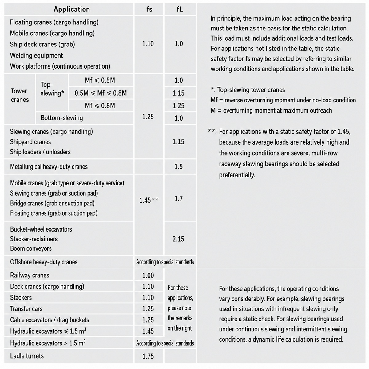
Note: fL is the dynamic safety factor, which must be used in conjunction with the dynamic load capacity curve. It is derived from experience and experimentation and is a reference value based on the maximum working load condition. If slewing ring selection based on service life is required, please contact our technical department.
Table 2
Technical Parameter Table for Slewing Ring Selection
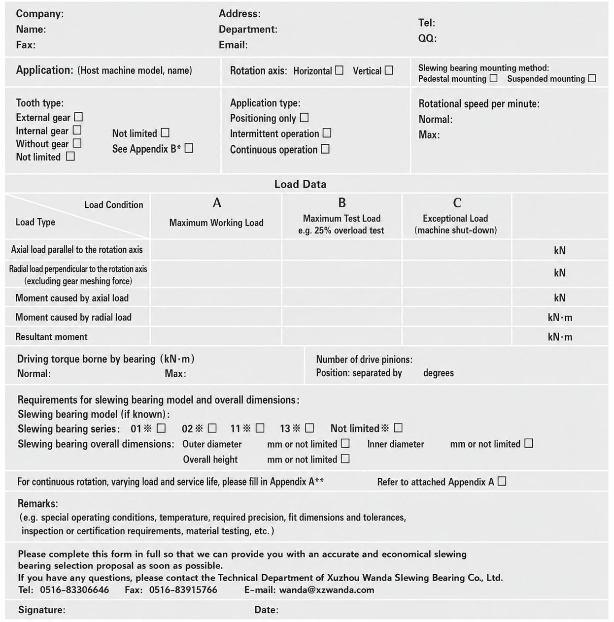
Note: Appendix B contains the parameters for the slewing ring and its mating pinion.
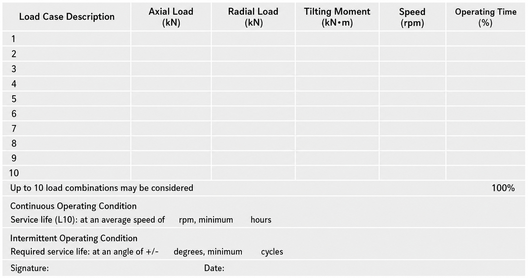
Appendix A contains the data table for the various loads on the slewing ring, their respective percentages of operating time, and the slewing ring rotational speed under each load condition.
Technical Parameter Table for Slewing Ring Selection Appendix A
Technical Parameter Table for Slewing Ring Selection Appendix B
Gear Description
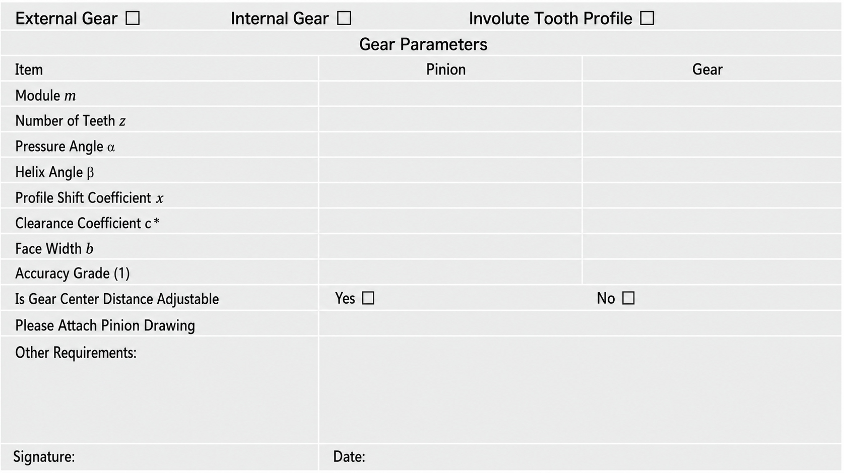
Note: (1) The recommended accuracy grade for large gears used in construction machinery is 11FH (per GB10095-88).
Slewing Ring Selection Calculation Example – Portal Crane (Grab Type)
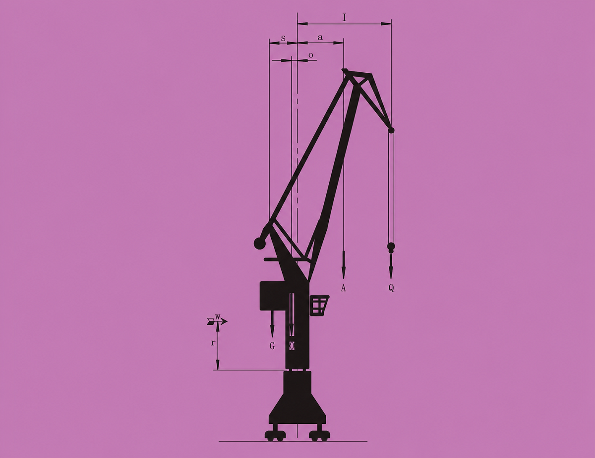
When using the load capacity curves for selection, the recommended method for calculating the maximum load is as follows:
Before selecting the slewing ring, first determine the static safety factor fs to be considered for this machine, which can be obtained from Table 1.
Portal crane (grab type): fs = 1.45
Given that the maximum static load occurs at the maximum outreach, the load calculation formulas are as follows:
1. Maximum working load considering Grade 8 wind force
Axial force
Fa = Q + A + O + G
Tilting moment
M = Q × lmax + A × amax + W × r − O × o − G × g
2. Load considering 25% test load without wind force
Axial force
Fa = 1.25 × Q + A + O + G
Tilting moment
M = 1.25 × Q × lmax + A × amax − O × o − G × g
Example: The working loads and outreach values of a grab-type harbour crane at maximum outreach are known as follows:
Q = 260 kN
lmax = 23 m
A = 75 kN
amax = 11 m
O = 450 kN
o = 0.75 m
G = 900 kN
g = 3 m
W = 27 kN
r = 6.5 m
1. Maximum working load under Grade 8 wind force
Fa = Q + A + O + G
= 260 + 75 + 450 + 900
= 1685 kN
M = Q × lmax + A × amax + W × r − O × o − G × g
= 260 × 23 + 75 × 11 + 27 × 6.5 − 450 × 0.75 − 900 × 3
= 3943 kN·m
2. Maximum working load considering 25% test load without wind force
Fa = 1.25 × Q + A + O + G
= 325 + 75 + 450 + 900
= 1750 kN
M = 1.25 × Q × lmax + A × amax − O × o − G × g
= 325 × 23 + 75 × 11 − 450 × 0.75 − 900 × 3
= 5566.3 kN·m
3. Maximum working load without wind force
Fa = 1685 kN
M = Q × lmax + A × amax − O × o − G × g
= 260 × 23 + 75 × 11 − 450 × 0.75 − 900 × 3
= 3767.5 kN·m
Load case 2 is selected as the working load for static calculation.
According to Table 1, a three-row roller slewing ring shall be used for a portal crane (grab type).
The static reference loads for the slewing ring are:
Fa’ = 1750 kN × 1.45 = 2537.5 kN
M’ = 5566.3 kN·m × 1.45 = 8071.1 kN·m
The bolt calculation loads are:
Fa = 1750 kN
M = 5566.3 kN·m
Based on the above calculation results, by referring to the load capacity curves, the slewing ring model 13*45.2000.002 can be selected.
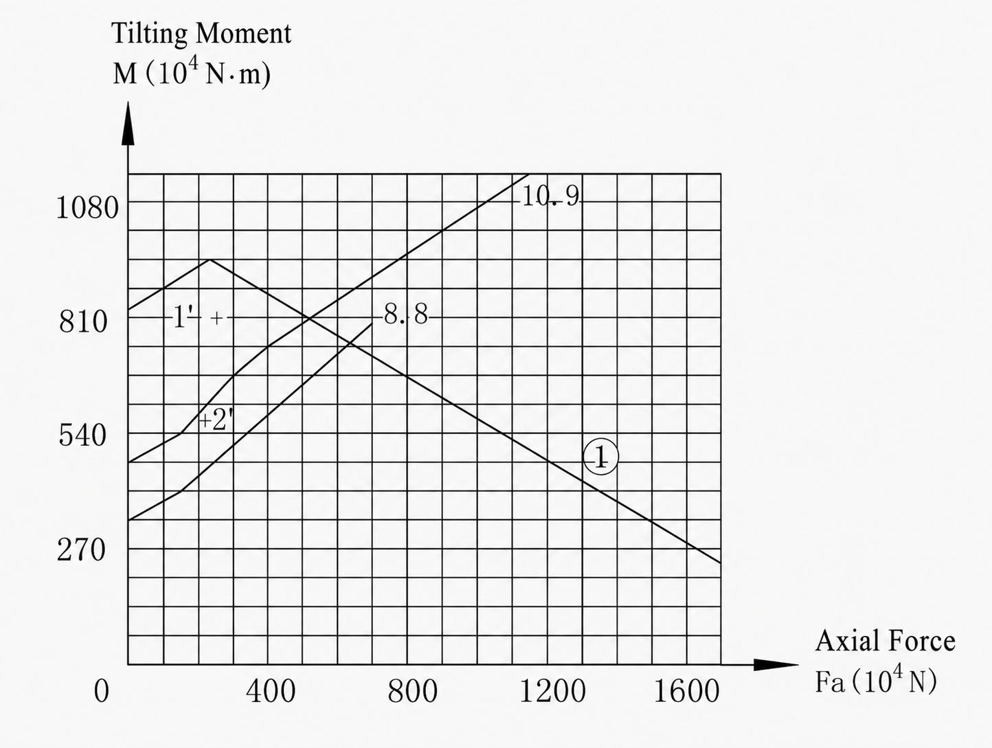
Line 1 is the static load capacity curve.
Lines 8.8 and 10.9 are the bolt load capacity curves.
Point 1′ is the static load point.
Point 2′ is the bolt load point.
Point 1′ lies below the raceway static load capacity curve 1, therefore the requirement is satisfied.
Point 2′ lies below the Grade 10.9 bolt load capacity curve, therefore Grade 10.9 bolts can be selected to meet the requirement.
Cart (0 items)